
Don’t Multiply MTFs (Unless You Know What You’re Doing)
Date
March 28, 2023
Author
Ben Masella
Time
3 min
Share this Post

If you have two optical systems and you’ve measured their individual MTFs, it can be tempting to think you can calculate the combined MTF of the two together. Unfortunately, that doesn’t always work.
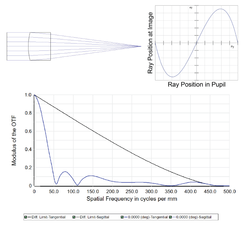
The modulation transfer function (MTF) of an image-forming optical system is a measure of how well that system transfers the contrast of an object to the contrast of an image. And, there are many situations in optical design where the object of one sub-system is the image formed by another. A common example is a telescope with an eyepiece. So, why not measure their MTFs individually to get the full system MTF? Have a look at the 10 mm focal length singlet in Figure 1. This lens has a ton of spherical aberration, which results in a relatively low MTF.
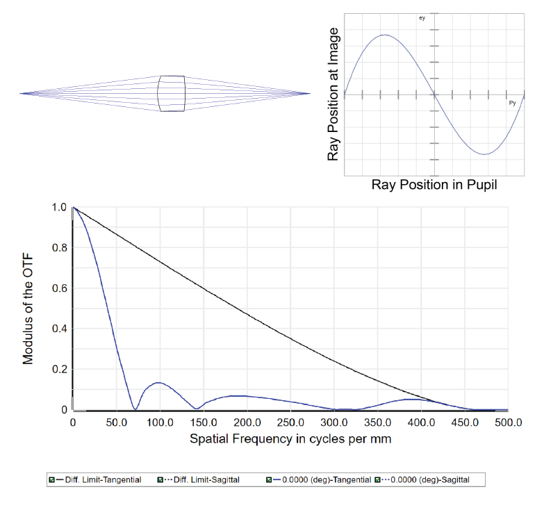
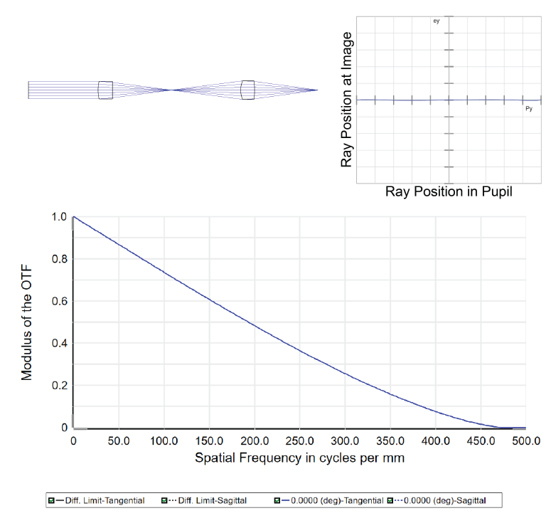
Now consider the aspheric singlet used at a finite conjugate in Figure 2. This lens was designed to induce spherical aberration that can compensate for that in Figure 1. It’s individual MTF is similar to the first lens. But, putting these together, we get the system shown in Figure 3. The combination is nearly diffraction limited on-axis. There’s no way to combine those two individual MTFs to produce the system MTF.
For those familiar with the use of symmetry in optical design, this is no surprise. Geometric aberrations are often canceled in this way. But, thinking of the optical system purely as a mathematical transform between object and image, why do the MTFs of the components fail to predict that of the full relay?
The answer is that the MTF alone does not fully describe the transformation from object to image. It is, by definition, the modulus of the optical transfer function (OTF). The full OTF of the system is a complex function, in the sense that it also includes an imaginary component that describes how the system impacts the phase of transmitted light. By calculating its modulus, or by measuring the intensity distribution, this phase component of the transfer function is lost. This is important because, in a combined system, the phase of the wavefront that enters the second half of the system is related to what happened in the first. That is to say, there is coherence between the two halves.
On the other hand, if coherence is broken, then it’s completely valid to multiply the MTFs of the two systems. For example, if a ground glass plate is placed at the internal image in Figure 3, the light will mostly scatter from that plane and coherence will be lost. The resulting MTF at the image plane of the combined system will be the product of the MTFs in Figures 1 and 2 (i.e., TERRIBLE). Another example would be if the intensity pattern at an image is measured and then reproduced and reimaged. This frequently happens in the palm of your hand, if you use a smartphone camera. The lens of your camera produces an image at its sensor which records the intensity pattern, then your phone displays the recorded pattern on its screen. Each of your eyes then reimage that pattern. If you measured the MTF of the lens in your smartphone and that of your eye, you could calculate the MTF of the combined system all the way to your retina.

But, while we can use MTFs to evaluate individual imaging systems, it does not contain enough information to determine the performance of a composite system when coherence is maintained. That requires measuring the system as a whole.
The good news is that Optikos has 40+ years of experience measuring the MTF of optical systems. If you need help evaluating, designing, or building yours, contact us today.
Written by Ben Masella, Ph.D., Optikos
Share this Post
See More Posts

Blog
Q&A: From Components to Complete Optical Subsystems: The Novanta and Optikos Collaboration
07/22/2026
•
7 min
Blog
Optikos Achieves Zero-Finding
ISO 13485 Recertification: A Conversation with Nick Mastrocola, Quality Manager at Optikos
07/13/2026
•
6 min

Blog
Advancing Automotive Imaging and Thermal Testing Insights from AutoSens USA 2026
06/24/2026
•
5 min