High-performance microscope objectives are critical to many life science imaging applications including DNA sequencing, spatial biology, super resolution microscopy, oncology diagnostics, and many other imaging modalities. The microscope objective is usually just one component in a complex imaging system used to achieve high-resolution imaging. Designing these imaging systems often requires a holistic and complex systems engineering development process and may include sensors, optical filters, motion stages, illumination optics, microscope objectives, and other mechanical/optical components. However one of the most important and often overlooked components of microscope systems is the coverslip.
In microscopic imaging, a coverglass or coverslip secures the specimen or object under investigation. A coverslip also introduces aberrations into the optical system, which must be corrected by the microscope objective. Commercial off-the shelf (COTS) microscope objectives are designed for a particular coverslip thickness (or for no coverglass). Some objectives are designed with a correction collar that allows the objective to be adjusted for a range of coverglass thicknesses. This applies to both air and immersion objectives.
Most of our life science customers understand that the nominal coverslip thickness needs to be considered during the design process of their microscope objective. Many customers have not considered how coverslip tolerances impact system performance. Smaller numerical aperture (NA) objectives, or lower resolution microscopes, are less susceptible to coverslip errors, whereas larger NA objectives, or higher resolution microscopes, may be very susceptible.
There are many important criteria that impact performance of your microscope imaging system including:
- thickness tolerance of the coverslip
- index of refraction and dispersion of the coverslip material
- autofluorescence of the coverslip material
- aqueous solutions that exist between the specimen and coverslip
- wedge of the coverslip
- surface quality of the coverslip
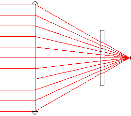
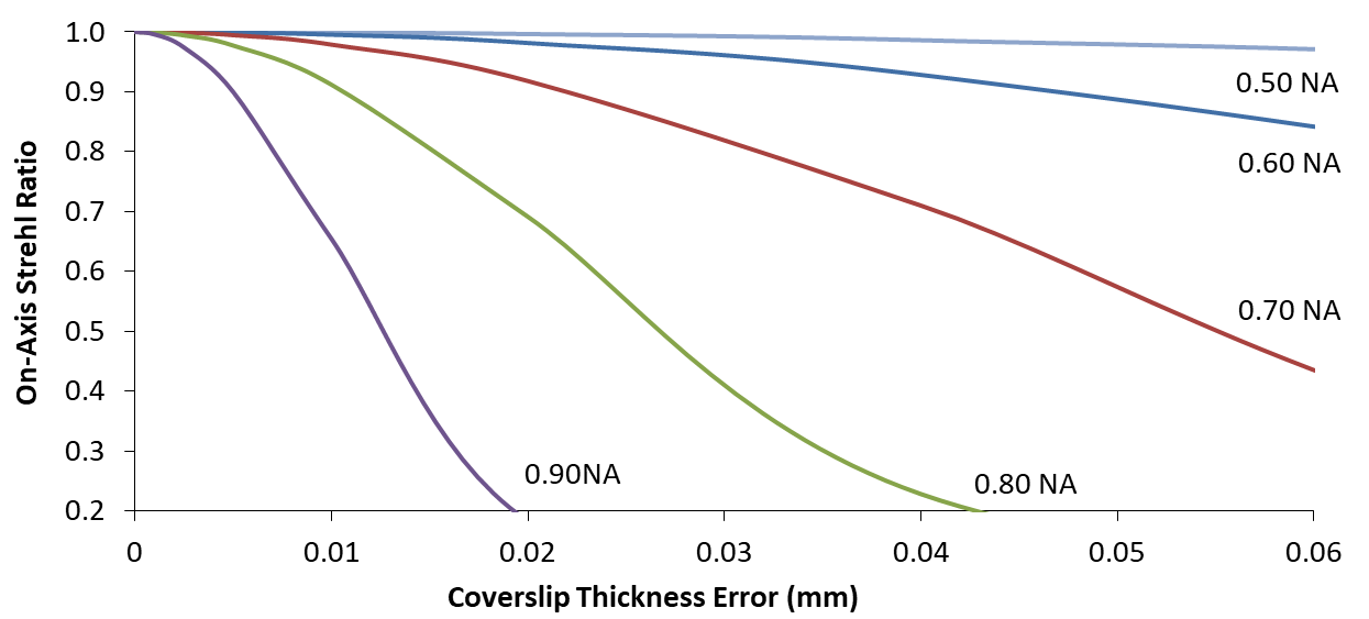
For high-resolution imaging, typically at numerical apertures greater than 0.5, the coverslip thickness tolerance is an important metric in your system performance budget. To demonstrate this, a paraxial or perfect objective lens, as shown in Figure 1, is used to simulate image quality as a function of coverslip thickness error for numerical apertures varying from 0.50 to 0.90. The image quality metric shown in Figure 2 is the Strehl ratio, which will vary between 0 and 1 for an imaging system. Imaging systems that are perfect, or completely free from aberrations, will have a Strehl ratio of 1. Optical systems with a Strehl ratio greater than 0.8, are said to have diffraction-limited image quality. Practically, this means that the imaging system has acceptable image quality and that geometric aberrations in the optical system are small. For some OEM applications where coverslip thickness sensitivity is critical to performance, there may unique system architectures wherein the coverslip thickness variability is actively compensated by optical components within the imaging channel.
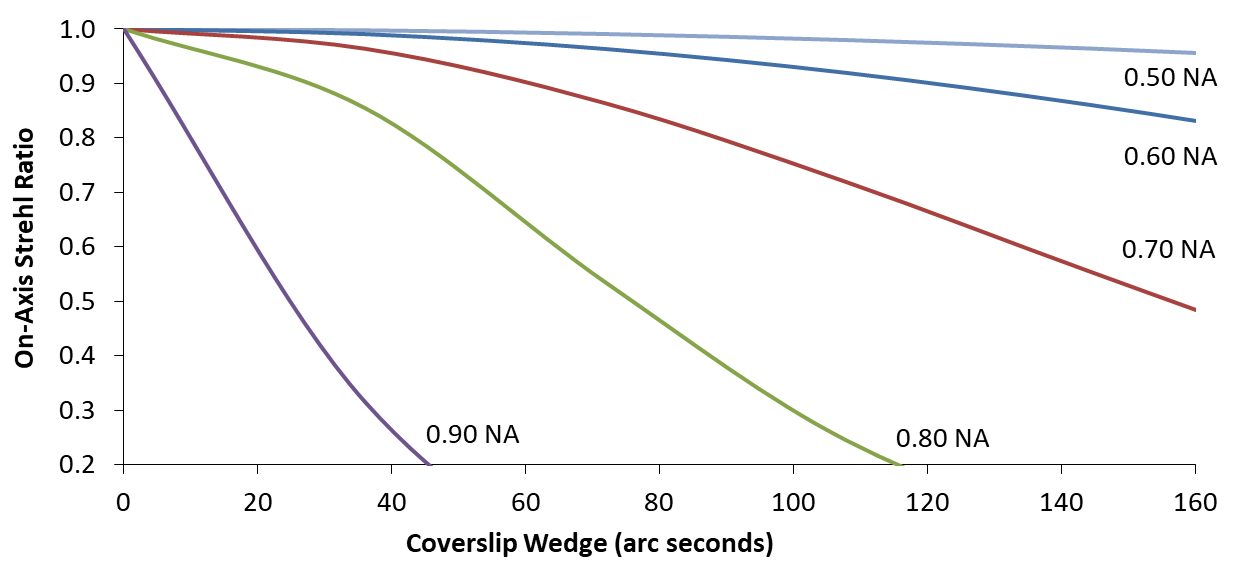
For high-resolution imaging, the coverslip wedge, curvature, or flatness across the imaging field of view, are equally important metrics in your system tolerancing budget. These optical tolerances are not intuitively correctable within the imaging optics of the microscope system. The impact on image quality from coverslip wedge, or the parallelism between the two surfaces of the coverslip, is shown in Figure 3. Again the Strehl ratio is calculated as a function of coverslip wedge for various numerical aperture objectives. One arc-minute of wedge may appreciably decrease the system performance for higher numerical aperture objectives.
Regardless of your imaging modality, it is important to properly model coverslip errors in optical design software and include them in your system tolerancing budget. In the case of many high performance microscope imaging systems, the results from these modeling efforts allow you to prescribe appropriate tolerances to the coverslip manufacturers and ensure your as-built performance meets expectations.
The engineering team at Optikos has designed and manufactured custom imaging objectives to achieve unparalleled image quality for a wide variety of applications. If you need guidance on how to properly model coverslip tolerances, or if you are interested in a custom microscope system for your next life science imaging application, contact Optikos today.
Return to Anywhere Light Goes blog.
Written by Anthony Visconti, Ph.D., Optikos Corporation

