I’ve spent a good deal of my nearly 20-year career here at Optikos working on high performance imaging projects. I’ve hammered out designs with our mechanical engineers exploring the trade space between the stiffness we’d like and the compliance we need. We’ve modeled the optical and mechanical tolerances on massive computer monitors with infinite zoom and all the best intentions. Parts are procured from reliable vendors and inspected and tested extensively, and finally, the day comes to put that all behind us and just build the first one.
I gown up and head into the clean room where I spend a surprising amount of time aligning the lens barrel on the center station. Then, I start stacking lenses, turning tiny set screws, and arguing with myself about the merits of chasing the last 2 microns of runout in an element. I stack a few more elements—everything is looking surprisingly good. Inevitably I hit that one element that just can’t get into place. Maybe it’s because there’s a hair too much wedge in the element. Maybe the lens barrel has a defect that’s pushing the lens off center. Maybe it’s all of the above and more, because when you’re looking for lens to lens alignment of 5 – 10 µm everything matters and no imperfection is too small.
Eventually I’m able to scrape and shim and deliver the high performing lens my customer needs. I got there, but it wasn’t efficient, and it sure wasn’t pleasant. And I think to myself “there has to be a better way.”
As it turns out, there is.
Traditional Lens Barrel
In a traditional, high-performance lens assembly, elements are stacked in a barrel with glass to metal interfaces that vary based on lens geometry. Alignment is performed on a lens centering station where each lens is either pushed laterally for centration or rolled about a surface for tilt using set screws. Each lens has a unique optical axis defined by the line joining its surfaces’ centers of curvature. The goal is to minimize the misalignment of each lens relative to a global datum.
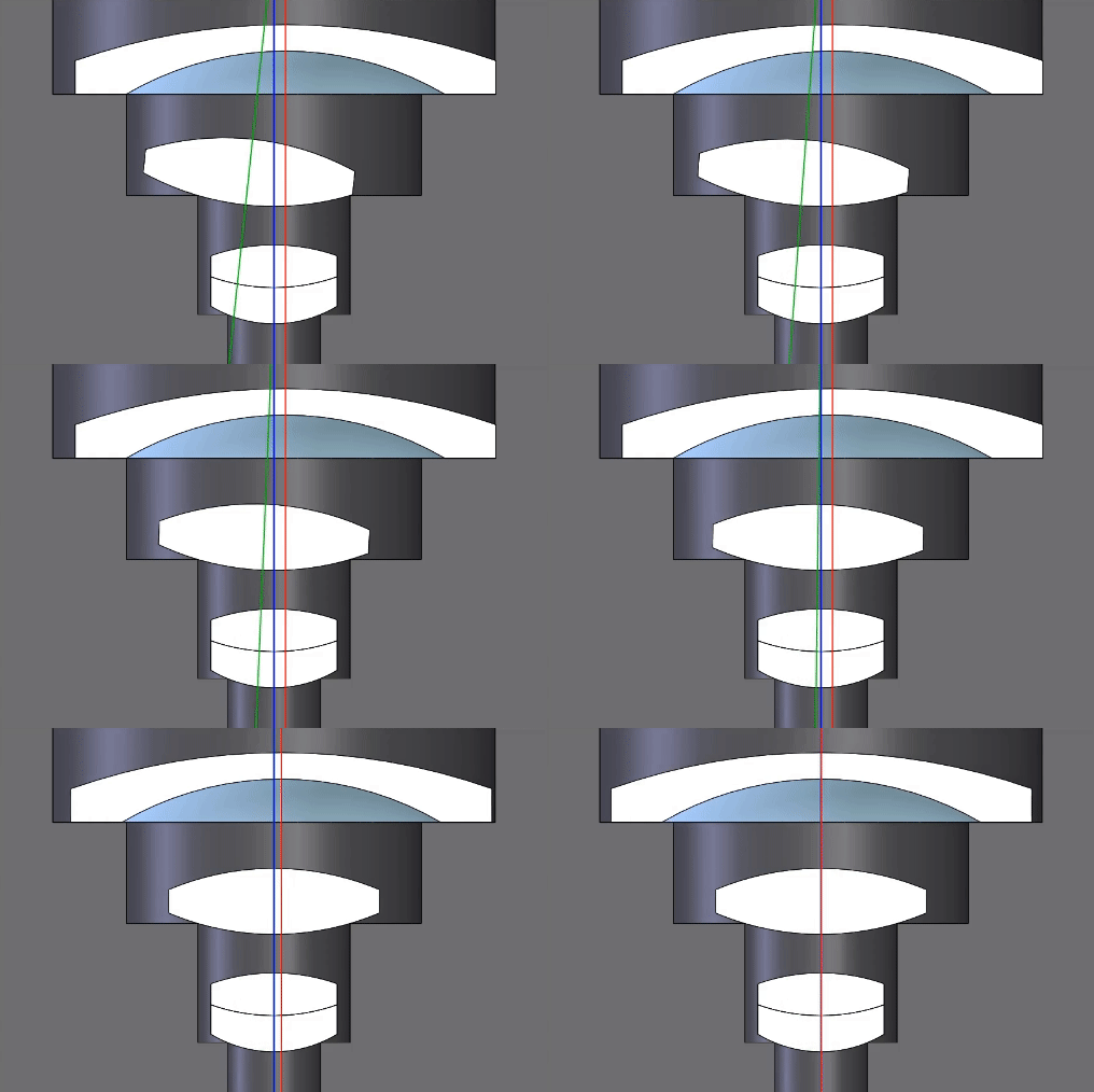
The animation below demonstrates how to achieve perfect alignment of a lens assembly when you have perfect parts.

Let’s first consider a bi-convex singlet in an edge contact seat in a lens barrel. If we assume all seats in the lens barrel are perfectly concentric then we can roll the lens about one surface until both are aligned. For a meniscus or negative lens, let’s assume the addition of an annulus. If the annulus is ground perfectly to the optical axis of the lens then we can push the element laterally until its axis is aligned to the rest of the system.

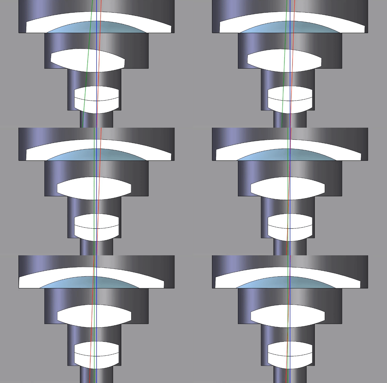
Now let’s get real and throw in some concentricity tolerance in the seat for our bi-convex lens and a wedge of the ground annulus in our meniscus lens. The second animation demonstrates that when we have real parts with non-zero tolerances you can nail tilt or centration of a lens, but not both. In practice lenses are aligned with a best compromise of tilt and centration, and you can’t discern their individual contributions. High performance lenses can be produced using this method.
However, the list of capable vendors will be short, component costs will be high, incoming inspection will need to be rigorous, and build time will be long and require skill.
Sub-Cell Mounting
In order to build this tightly toleranced lens we need discrete adjustment of lens centration and tilt. There are a few ways to accomplish this, but the most straight forward method is sub-cell mounting.
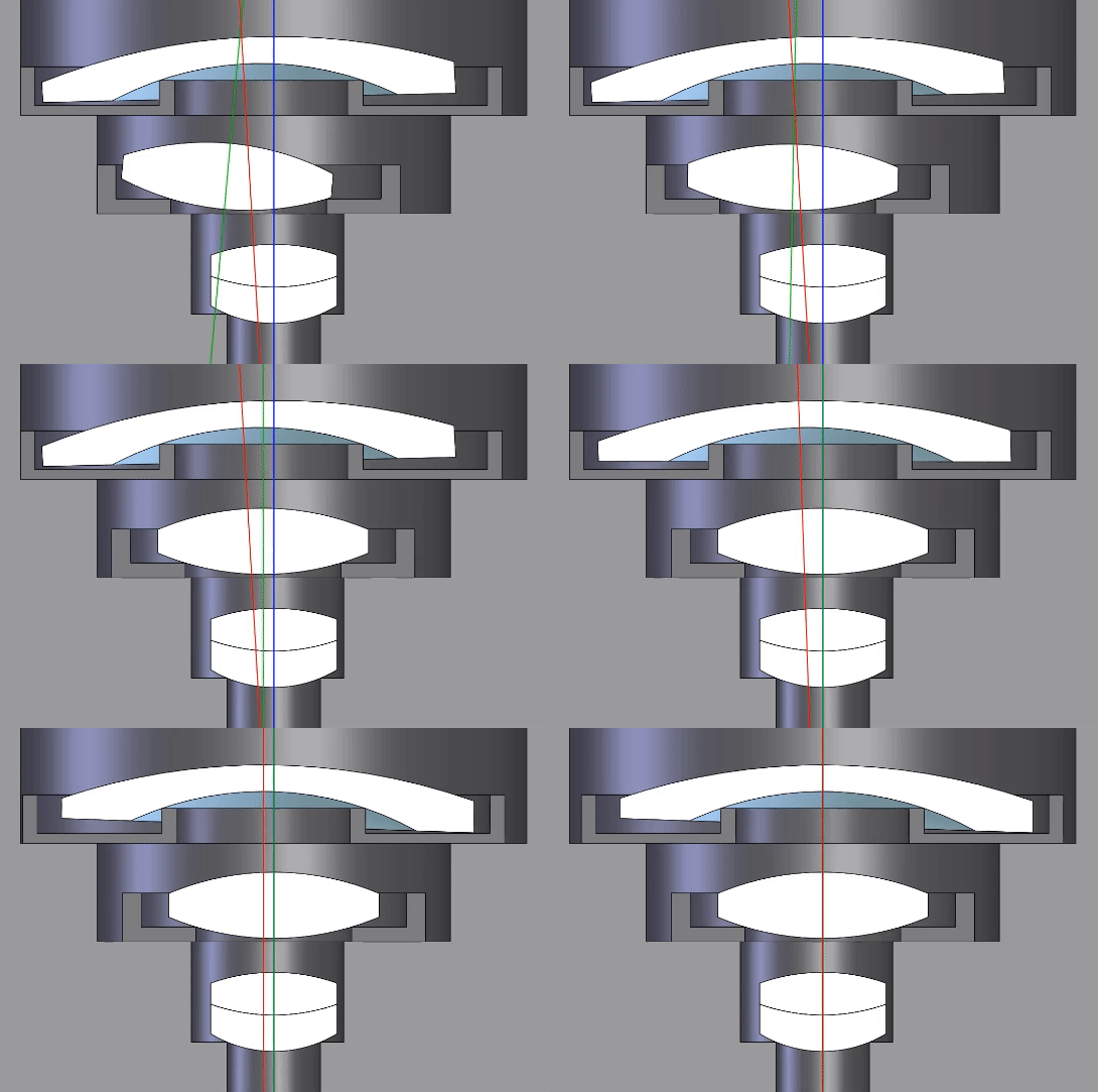
In this scheme each lens is mounted in its own cell, and the cells are mounted in the lens barrel. Each lens is rolled for near zero tilt in its cell on a centering station. Then lens cells are stacked in the barrel and pushed radially for centration to the global datum.
This method seems like it should work—we have separable alignments for centration and tilt, and can also remove tight tolerances on the meniscus lens annulus and lens barrel concentricity. Very high performance lenses can be produced using this method. The list of lens vendors can be opened up, and lens cost should come down.
However, mechanical interface surfaces on the lens cells and barrel seats must be flat and clean. Aspect ratios on the cells are usually not great for machining, and some hand lapping to remove the chuck print through may be necessary. Additionally, parallelism of seats in the lens barrel is critical and all burrs or machining marks must be removed. Certainly, this method can yield higher performance vs. traditional methods, but this comes at the expense of labor and is not suited to high volume.

Alignment Turning
Finally, we’ve come to that better method we were searching for. Alignment Turning uses all the advantages of Sub-Cell Mounting, then adds a few more features and automates the process of a few hours into just a few minutes.
At the heart of Alignment Turning at Optikos is our Innolite IL-300 Alignment Turning Machine. It’s a 3-Axis Diamond Turning Lathe with onboard optical metrology to locate the optical axis of a lens. Lens cells are oversized and do not require tight tolerances.
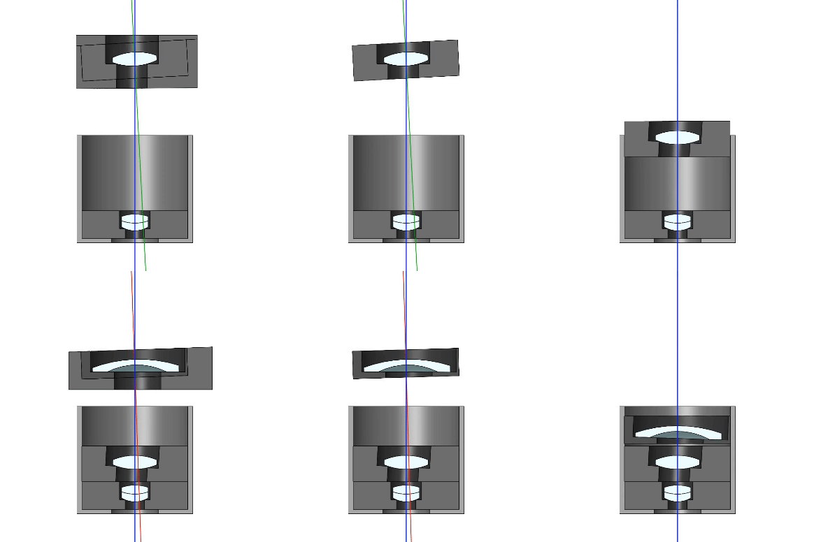
This is the process: first, lenses are retained in Sub-Cells. Next, the cell is diamond turned on the front and rear faces and OD such that the cell critical dimensions are centered and de-tilted relative to the lens to within 2 microns. This manufacturing method can greatly simplify the mechanical design.
The lens barrel can now be just a tube with tight tolerance on cylindricity. Additionally, the sag from each lens surface to the adjacent cell face can be controlled to just a few microns. This allows for custom and highly accurate airspace control between lens elements. Custom airspaces can correct for tolerances in radius, center thickness, and glass melts.
Airspace compensation opens up lens tolerances and allows for re-optimization of each build to maximize performance. Lens cells are then stacked sequentially in the simplified lens barrel with a tight slip fit to maintain centration.

The final product is a perfectly aligned lens system, completed in a fraction of the time of a traditional alignment process, with far fewer headaches and hiccups along the way.
Alignment Turning enables Optikos to produce our highest performing lenses to date, with elements spaced accurately within a few microns without the need for hours spent on the alignment stations. Best of all, we can do it at scale for less, which means a cost savings for our customers without a compromise in performance.


